Designing a Composite Structural Chassis
Composite chassis are never recommended for new teams due to their complexity and the amount of time needed to verify that they are strong enough. Composites are like 3D prints in that their properties rely on so many factors that experimentation is mandatory. However, we decided to take on the challenge for the following reasons:
- We were not allowed to weld on campus due to safety issues. The alterative steel or aluminium frame would have been a logistical nightmare.
- Our university had an FSAE team that used a smaller steel-frame chassis, and we were under pressure to distinguish ourselves by providing a different experience.
- We didn’t have money to buy a steel chassis early on, so we could spend the time performing lower cost experiments to better understand composites.
Finding an Ergonomic Shape
The first step to the design process was figuring out dimensions that would fit a person, and design objectives for the overall vehicle. I found dimensions by looking at anthropometric data online, and designed the car to fit the 95th percentile male. I also measured myself in different seating positions and created a rough model in CAD with movable joints.
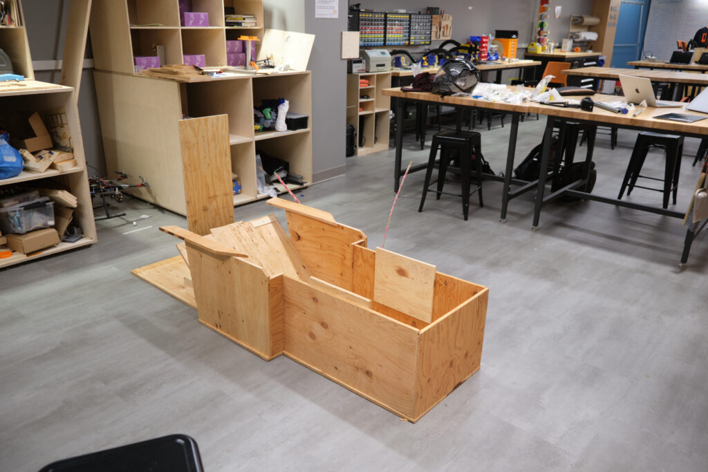
The mockup chassis made from plywood.
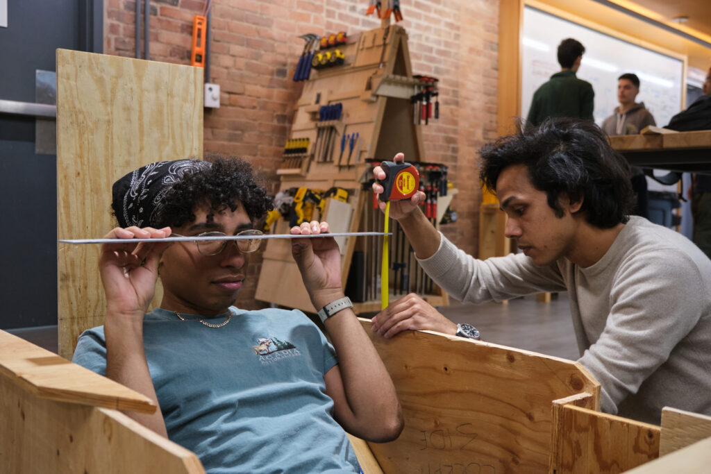
Measuring eye height. Regulations dictate a minimum eye-height from the ground. We tried to design the seat such that the lowest driver’s eye height was just above the minimum, helping lower the center of gravity.
After this, and in part because of our lack of funding at this stage, we built a wooden mock-up chassis so we could verify the ergonomics of the car and show our progress. This chassis was made from plywood, so we could easily add, remove, or move sections to find a shape that worked. We sat several members of our team into it and collected their feedback on the comfort of different positions.
From assigning material weights, I found that the position of the driver had a huge influence on the height and position of the center of gravity. A low center of gravity means that we can achieve the static stability regulation determined in the regulations with a narrower wheelbase. As a narrower wheelbase means reduced frontal area of the car, this massively helps reduce aerodynamic drag.
Characterizing Carbon Fiber
The problem:
- Carbon fiber is orthotropic, and properties are not easily found online.
- The moduli and ultimate strengths is different for each combination of fiber and resin.
- The strength of the resin depends on external factors like temperature and cure cycle.
- Defects massively impact strength, but we do not have access to non-destructive inspection techniques.
- Pre-made panels may have datasheets but they are usually incomplete for composite FEA and are expensive to buy and ship.
- We do not have a large oven, so industrial pre-pregs are not an option.
The solution:
- Find the best way to manufacture composites by making samples using the wet-layup and resin-infusion processes. Choose a single affordable and available resin and fiber.
- Carry out formalized ASTM test D3039 to compare manufacturing methods and collect UTS, tensile modulus, and Poisson’s ratio data for our selected carbon fiber and resin combination.
- After selecting the stronger manufacturing method, conduct ASTM D3518 to find the in-plane shear modulus.
- Input the values into static “collision” simulations in Altair Hyperworks. Optimize the layup based on stress and the Tsai-Wu failure criterion.
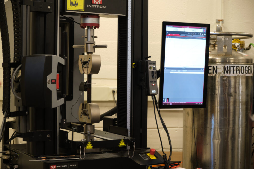
D3039 Test setup on an Instron with an extensometer
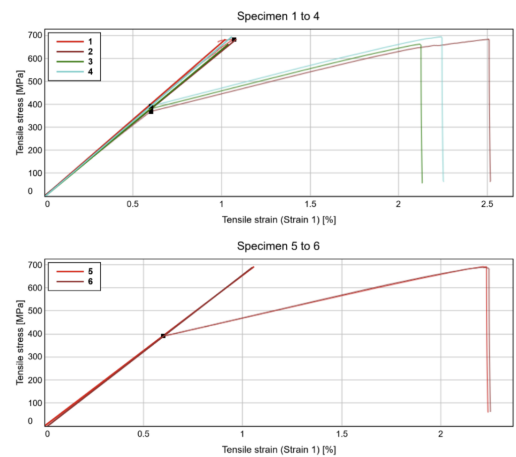
D3039 Data processed in MATLAB
Destructive testing of carbon fiber samples to find Ultimate strengths and Moduli.
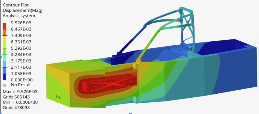
Deflection plot of a static 5G collision tests with layup optimized, a solid roll cage with bolts modeled, and with constraints at the suspension mounting points.
Building it
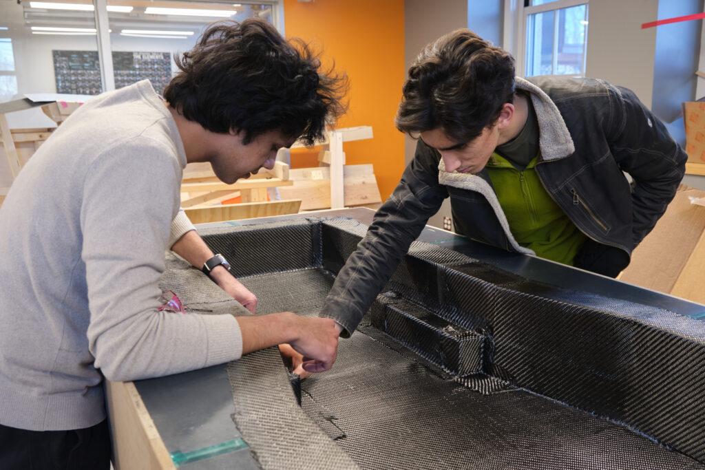
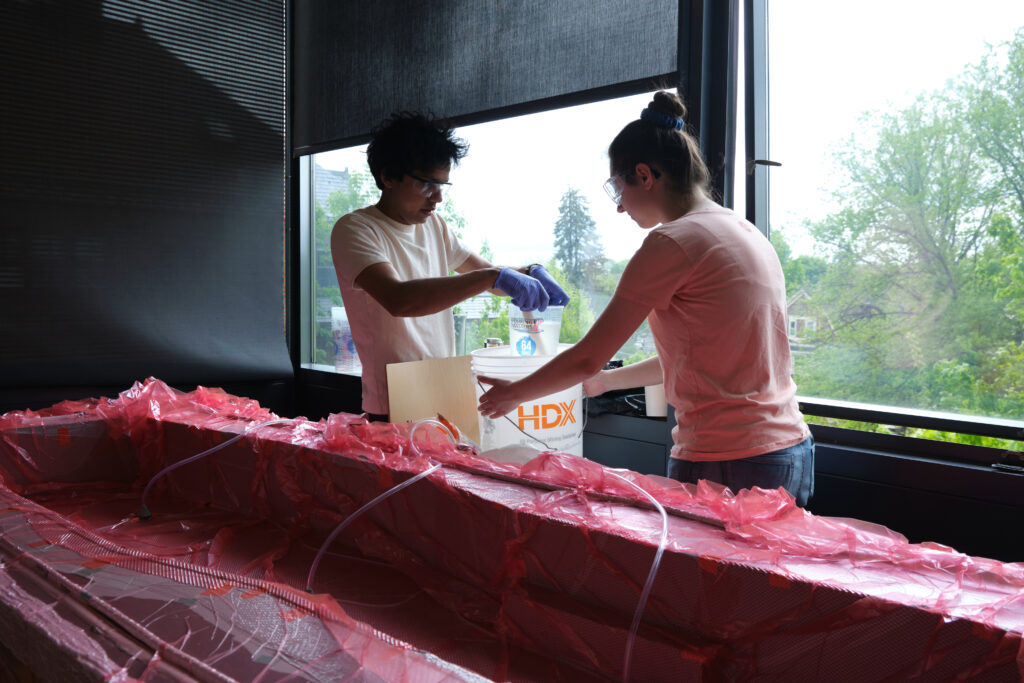
Laying up carbon fiber fabrics into the mold.
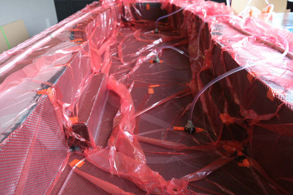
The resin-infused chassis. You can more clearly see the resin inlets and the channels and mesh we used to distribute the resin. The resin fully saturated the carbon fiber – take a look at the left edge to see the resin fronts.
Mixing resin during the resin-infusion. The mold is put into a vacuum bag with an outlet on one end. We distribute resin inlets throughout the mold and use the vacuum to pull resin through dry carbon fiber fabric.
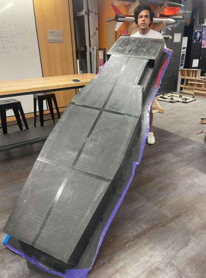
The end-result. The matte texture is of the release agent and would be wiped off.
Failures
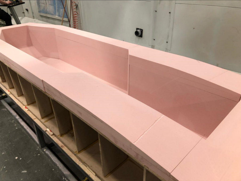
The process of characterising the material to building the structure pictured above took over a year. We had a host of issues that kept pushing back deadlines. The mold was made from panels of MDF that formed 90-degree angles. This was done to cut costs but as there were no draft angles, this necessitated splitting the mold into at least 6 sections.
- After gluing all the pieces together, they did not line up well and were often warped.
- We solved this by creating a flat reference table and sanded the sections until the floor was aligned. Then, we patched the gaps with wax or bondo.
- After many attempts, we could not get the mold to seal due to small gaps between the pieces, which made pulling a vacuum impossible. Without a full vacuum, we would not have been able to do a resin-infusion and make the carbon part.
- We solved this problem by creating an envelope bag and covering both the top and bottom of the mold. However, this put the whole mold in compression due to atmospheric pressure. The structures we made collapsed twice and punctured the vacuum bag several times.
- After adding reinforcement, we could pull enough vacuum, but were forced out of the maker space as it was the summer. We hauled the mold up to a study room to carry out the infusion. The study room was beside a professor’s office who complained about the noise of the vacuum pump several times. It took some negotiating to figure out.
- The infusion itself ran well, but we found out that resin had seeped through the gaps between the molds and fused them together. We had to destroy the mold to get the part out.
- We needed the mold to create a second half that would form the full chassis. We either would have to remake the mold.
- Regulations changed the summer in which we did this infusion. This meant we had to make new design changes that rendered this chassis design obsolete. We had to start from scratch. This piece would end up being sacrificed to carry out more material testing.
Lessons and the Second Iteration
The main lesson I took from the failure of the first chassis was that risk is worth money and simple systems help alleviate that risk. In our attempts to reduce material costs, we added complexity by having several pieces attach together, but we were not practiced enough in identifying and overcoming those mistakes before we made them.
For the next iteration, I decided to keep it simple. I found a machine shop in Rhode Island that makes composite tooling with large CNC machines, and I had success in getting a sponsorship of tooling board. This new mold is just one piece. We would create a frame, then bond tooling oversized board sections to it. The machine shop would then machine the stock to a mold with sufficient draft angles. We would only have to use the mold once and there would be a nearly zero chance of leaks as long as we seal up the surface correctly.
The newest chassis mold.