Scratch-built Electric Motor
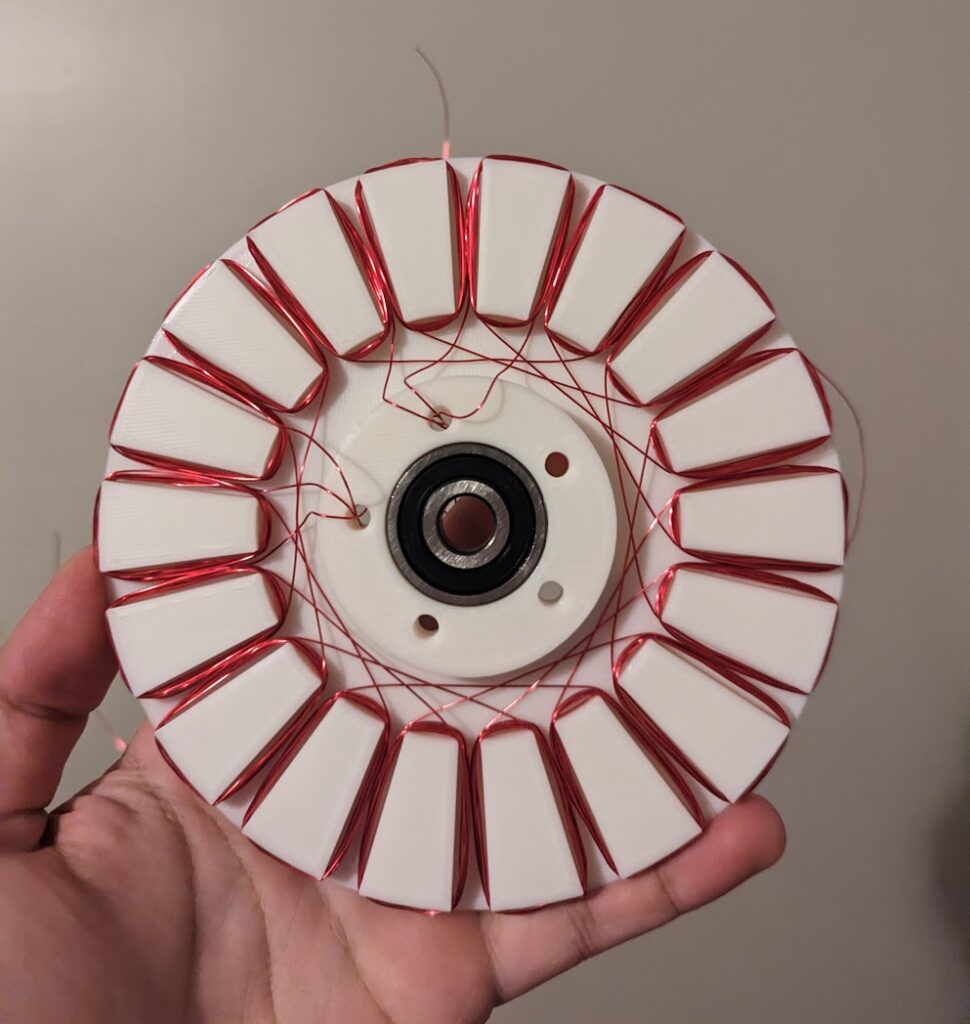
3D Printed small-scale stator for a concentrated winding axial-flux machine. I used this to better understand the working principle of motors and how they are wound.
Why?
There are no other solar car teams in America that make their own motors for single-seater solar car. To most people, including me a year ago, this task seemed unrealistic and complex. However, the upfront cost of a dedicated hub motor for solar cars was exorbitant; there are only two companies that make them, and both were far beyond what we could afford.
I was inspired by some videos I found of hobbyists making 3D printed motors for drones. As I had a 3D printer, I decided to dabble in creating my own design. I watched a lot of videos explaining the working principles and basic equations, designed a simple system, and bought some iron-filled PLA, enameled wires, and magnets.
While I didn’t have time to finish this prototype, I found an alumni from Missouri S&T who built their team a motor. With his help and by looking at other teams in Europe, I became confident enough to have a crack at making a full-scale motor for our solar car that would save us upwards of $7000.
Establishing Parameters
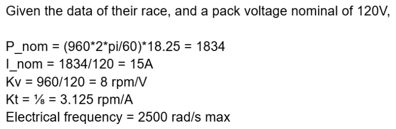
The gold-standard motor in the solar car world is made by Marand. The design of the motor was done by CSIRO and is fairly old. I found a set of slides online and reverse-engineered it to figure out what they had done. For example, I could tell their motor had 20 poles and 20 slots, and I knew what the general diameter of the magnets were. I could also tell the velocity constant (Kv) and torque constant by looking at their datasheet.
I coupled this by looking at a paper written by members of the team Vattenfall in the Netherlands. While they don’t create their own motors, one of their team members created a housing for their Master’s thesis. This included data on their motor’s average speed, torque, power consumption, and efficiency as they participated in the World Solar Challenge in 2009. A quick calculation helped me find their Kv.
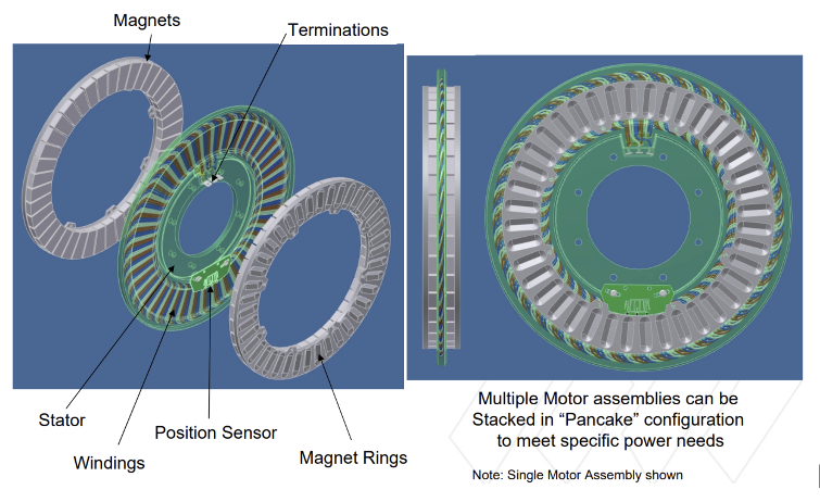
Drawings provided in a presentation by Marand discussing the motor. It’s a simple design with nothing proprietary or patented.
Given all this information, I decided to make a similar axial-flux machine, but using MATLAB, design the motor to a target Kv, Kt, and maximum speed.
Analytical Model in MATLAB
This axial-flux motor is ironless and coreless with distributed windings. In other words, it produces rotation by simply passing current through wires perpendicular to a magnetic field. This makes modeling the motor easy as there are no core-losses, and we can use simple equations such as F = ILxB and expand on them to create an analytical model.
I could easily change variables such as the number of poles, number of turns, and the inner and outer diameter of the magnet rings, then see how it influences the length, the current and torque constants, and maximum thickness of the wires, which then would influence efficiency, maximum speed, and power.
The only value I could not easily find through quick math was the magnetic flux between the two rings of magnets. Here, I used a simulation in COMSOL Multiphysics. I did a simple 2D simulation where I “unrolled” the magnet rings on the line of the average radius. I assumed the remanence values for N52 magnets on sites like CMS Magnetics were accurate, and inputted the direction of the magnetic field for every magnet. By probing the results, I could find the maximum flux at the center of the gap, and validate that the magnet orientations would give me a sinusoidal waveform required for efficient operation and low torque ripple.
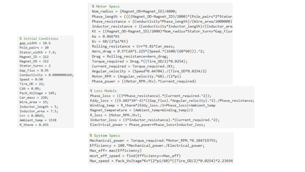
MATLAB script to model the motor
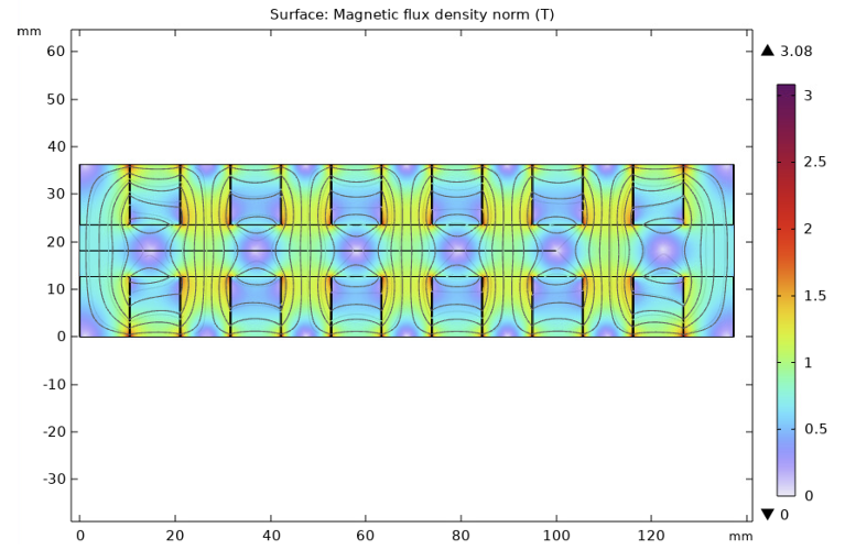
COMSOL Simulation of the magnetic field. This simulation included a Halbach array.
First Prototype
With the parameters established, we purchased custom-shaped magnets that were of the right shape and size for my design. I also sourced Litz wires optimized for the electrical frequency at which the car would operate at. This is essentially a bunch of enamelled and insulted wires bunched and twisted together to reduce the skin-effect produced by the alternating current of the phase. In this situation, I sourced compacted Litz wire that was shaped to a rectangular cross-section such that I could fit more wire into the stator and reduce copper resistive losses.
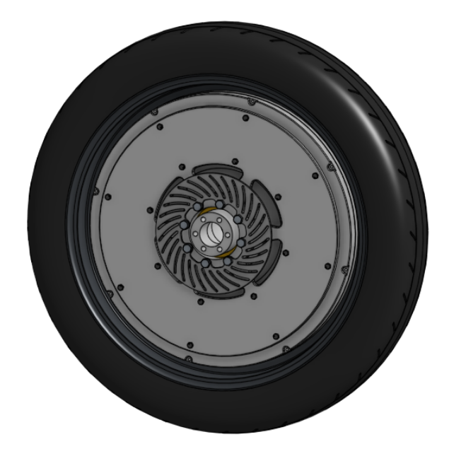
I designed a housing with a relatively large amount of aluminium behind the magnets to both add rigidity to resist the deflection caused by the Halbach array, and to act as a thermal heat sink to keep the magnets cool.
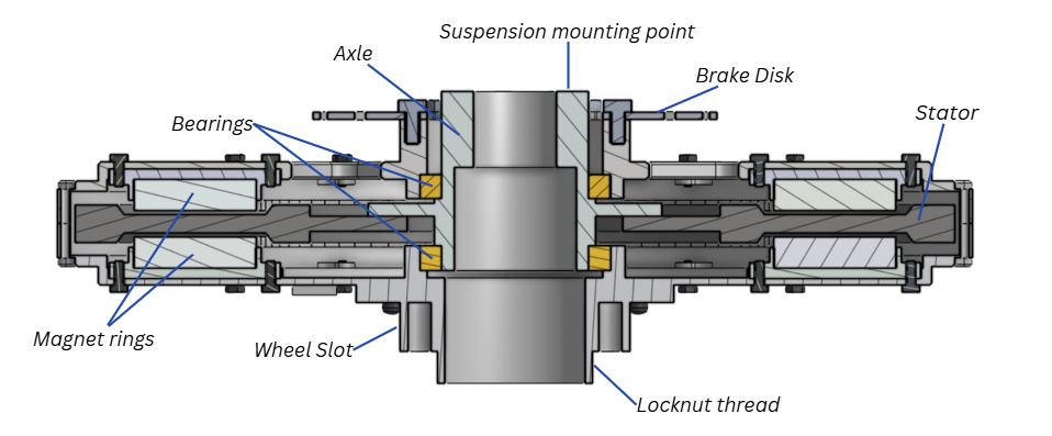
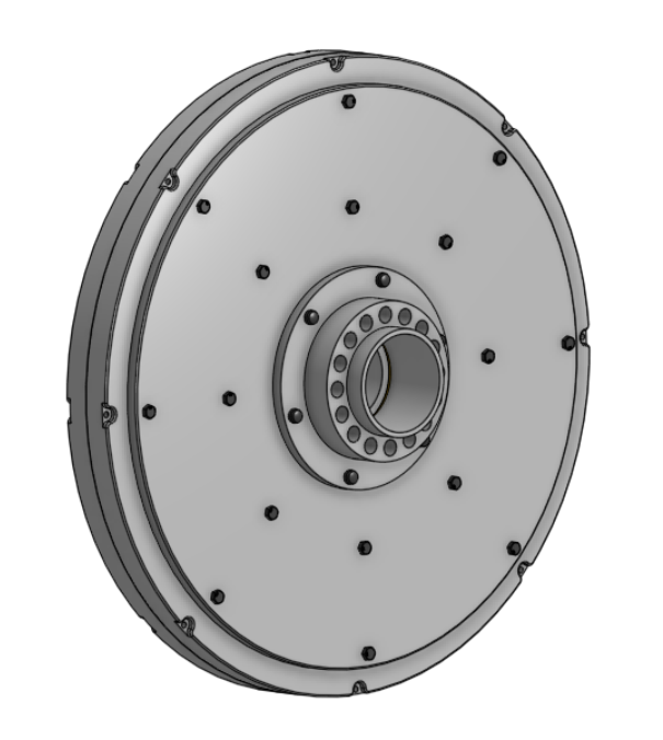
CAD model of the motor. Not pictured is the fact that the stators have windings embedded in them.
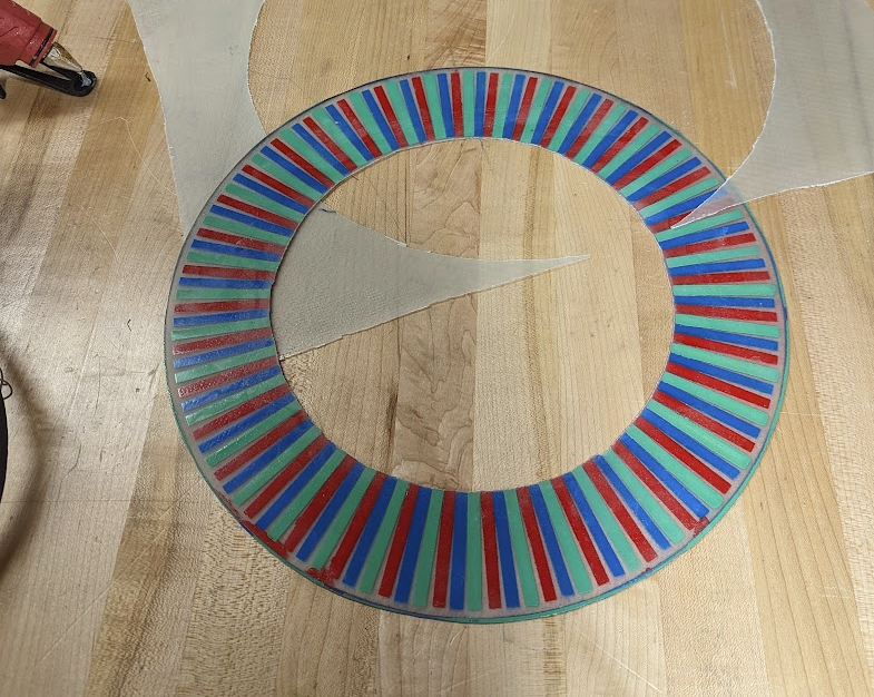
Stator Core. I didn’t photograph the template and painting process although in hindsight I should have.
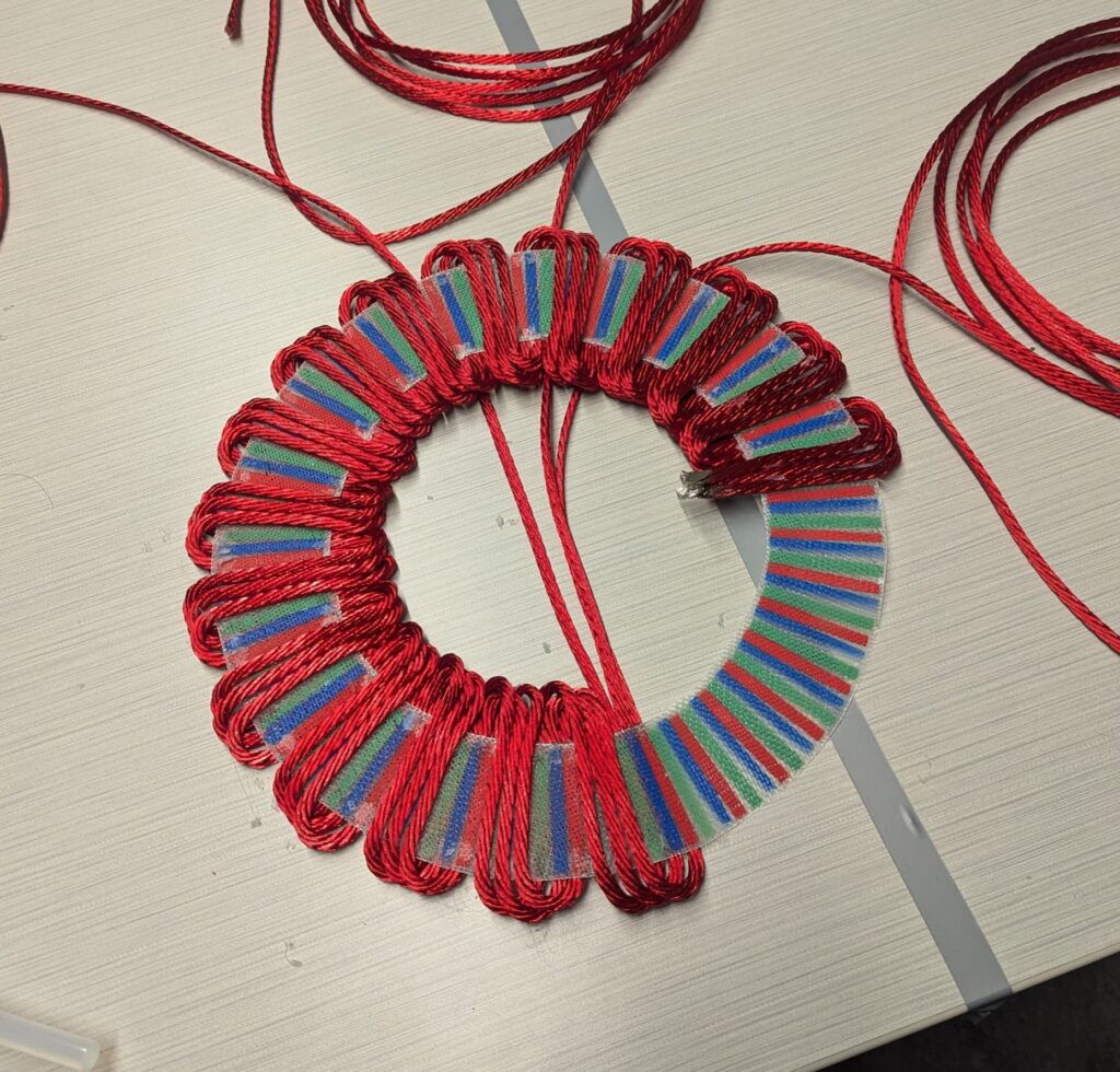
Half-way through winding the stator
Manufacturing the Stator
To make the windings, I first created a fiberglass sheet with a resin infusion. This sheet was meant to be the structure around which I would wind the wires to make the stator. To know the positions at which to lay the wires, I designed the following process:
- Laser cut a mask that has holes that correspond to the positions of the wires of each phase. Also include two more holes that are rotated by 120 electrical degrees from the first phase.
- Mask the two extra holes with masking tape.
- Spray paint the fiberglass sheet with the laser cut mask, covering it in one colour. This would provide a visual guide for where every wire in the first phase should land when winding.
- Remove the tape over the extra holes. These holes are aligning features for the second phase.
- Rotate the mask until the extra holes line up with the previously painted strips.
- Spray again in a different colour to provide guides for the second phase.
- Repeat the process for the third phase.
- Measure three 9m strips of wire and cut them off the spool.
- Dip one end of the wire in a hot solder pot to melt the enamel and cap the ends.
- Place all these ends near the edge of the inside of the core. This is the Y-termination point.
- Line up the wires with the guides and hot glue them in place with two small dabs of glue each.
- Flip the core and bend each wire until they line up with the guides on the other side. Glue these in place
- Flip the core again and pass each entire phase through the center of the core. Bend the wires and glue them again.
- Keep winding until you reach two full turns. There should not be any paint showing on the core.
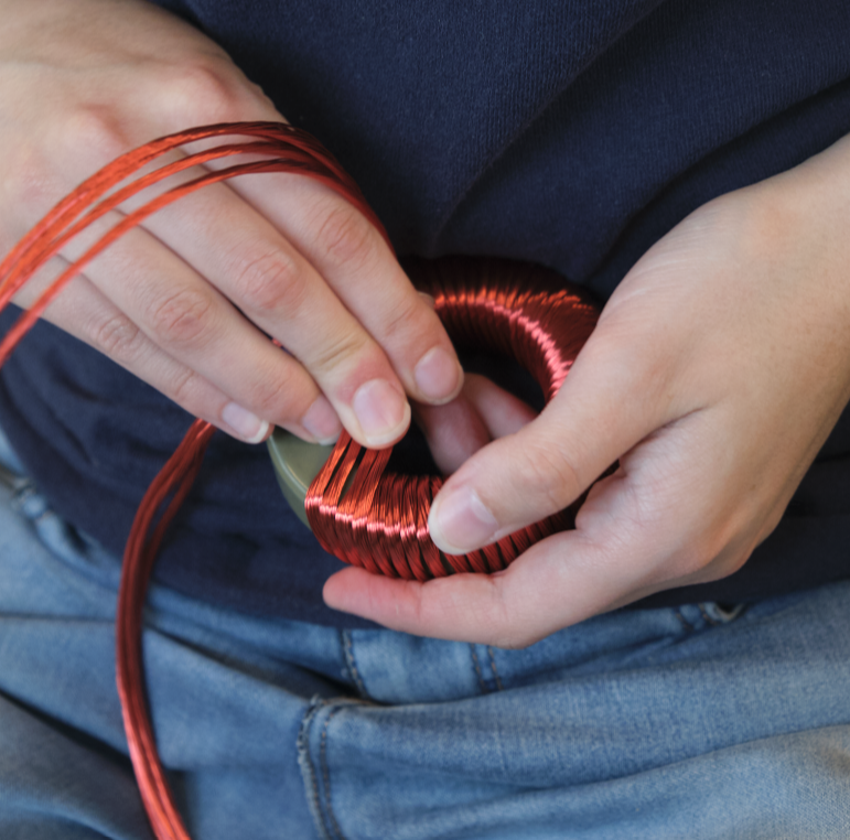
Winding a large toroidal inductor with Litz wire to increase motor inductance.
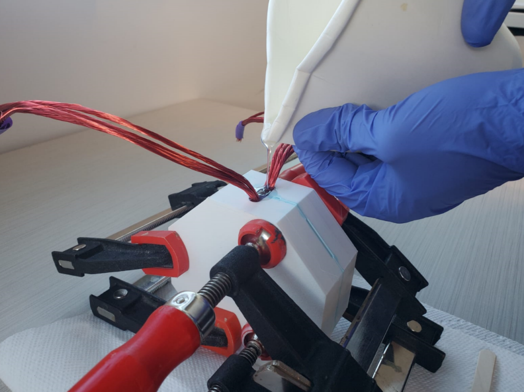
The wound inductor is placed in the mold, clamped, then epoxy resin is poured into it.
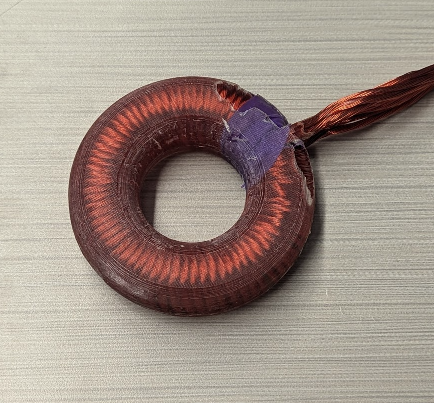
The cast inductor. The casting was not fully filled due to air bubbles releasing during the cure. It was a successful proof of concept that gave confidence for casting the stator with the same method.
Manufacturing the Housing
I made the call to outsource machining the housing as it was quite complicated and large, and would have taken us a lot of time to manufacture. I did make some crucial mistakes in my first iteration, however. To reduce costs, I decided to split the housing in multiple sections to reduce material wastage from machining. This, however, meant that there were more parts to fit with each other, and I did not properly tolerance the interface between them. As a result, some of the parts fit far too tightly. Trying to force them into place with a hydraulic press made the housing warp and develop too much runout and misalignment.
In the next iteration, I reduced the number of parts and interfaces, and added alignment features to ensure they lined up. I also separated the magnet rings from the assembly. Instead of the magnets being directly bonded to the housing, I would bond them to a circular plate that can be screwed into a slot in the housing. This alleviates the risk of the housing going wrong and reduce the cost of repair if there is a failure of the bond between the magnets and the housing.
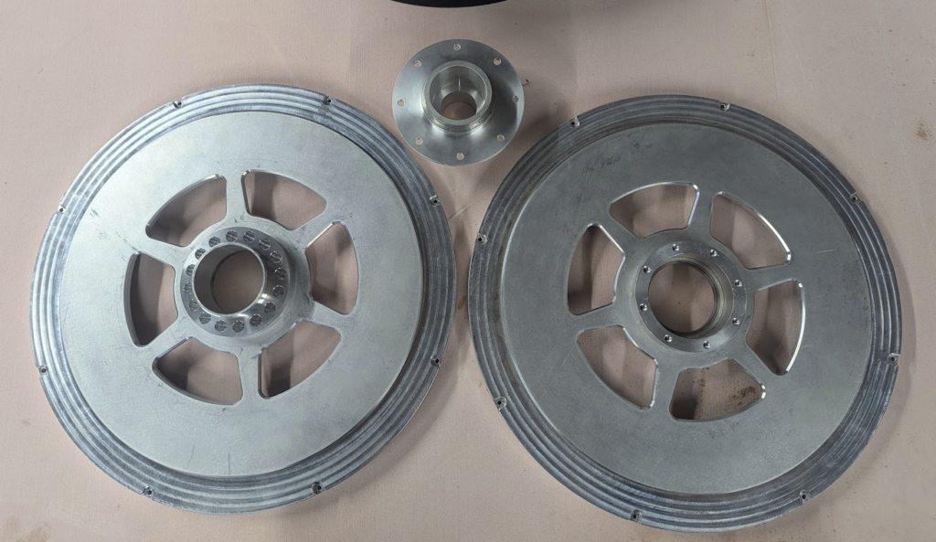
The housing is made from two halves, each with a splied connection. This allowed me do design different interfaces to fit a brake disk to one side and the wheel to the other side.
In the next iteration, I did away with the splined connection and instead will make two larger parts that self-align.
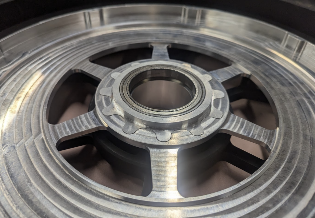
The spined connection between the parts was not appropriately toleranced, so they fit far too tightly and made the housing bend. The two halves developed too much runout and did not line up.
I will however be screwing in the magnet rings instead of bonding them directly to the housing. This alleviates risk.