Tufts Solar Vehicle Project: Wheel Rims

Introduction

Wheels proved to be one of the most expensive parts of the car, with companies charging on average $1,500 per rim. I started designing wheels as a cost saving measure but found it to be a lot of fun. This was an exercise in honing my CAD and FEA skills, while performing cost analyses and optimising the final product to the highest possible degree. 

Design Constants

Solar car rims are usually standardised at 16″, following the 90/80 R16 bead profile. This means the width of the tire is 90mm, with the aspect ratio (tire height/rim width) is 80. I found the bead profile of Michelin solar car tires online, and had some very valuable input from University of Minnesota’s Solar Vehicle Project and University of Michigan’s Solar Car team for an idealised rim profile.

Metal Rims: Iterations

Metal Rims: Testing Methodology

With the help of UMNSVP, I created a testing suite to optimise the rims. This models three key fatigue tests that are carried out by a rim testing standard – JASO T 203-85. This standard can be readily found online. According to the standards, certification to a specific load rating requires passing five tests:

  • Durability Against a Bending Moment
  • Durability Against a Radial Load
  • Impact Resistance
  • Durability Against a Torsion Moment
  • Airtightness of Rim

To keep it simple, I did not do impact simulations, and airtightness is something we can test for after the rims have been made. The focus on the FEA will be in durability against bending, radial, and torsional loads that mimic cornering, bump, and braking loads respectively. 

The standard describes what a test setup looks like for each test instance.

When mounted on a car, the forces of bumps and corners are always applied at the contact patch between the tire and the ground. This point remains constant relative to the vehicle, but the wheels constantly rotate. If we use the wheel as a reference frame, however, we observe that any point along the edge of the wheel undergoes a cyclic load (assuming the load is distributed by the tire). We can model the forces the wheel experiences as it rotates as a fatigue test at a specific orientation with fully-reversed cycles. Below are Von-Mises stress plots that show the results of the three tests.

Material Selection

As fatigue was the primary failure mode, I found that the standard aluminium 6061-T6 was not the best option. After some digging, I found data to guide this decision in the Metallic Materials Properties Development and Standardization (MMPDS) book. This had experimental data on the S-N curves of multiple alloys. Through sieving through charts, I narrowed down my material selection to:

  1. 2024-T3 Aluminium. Moderate yield strength, moderate unnotched fatigue life, high notched fatigue life.
  2. 7075-T6 Aluminium. High yield strength, high unnotched fatigue life, moderate notched fatigue life.

In other words, 7075 was stronger overall and would withstand higher shock forces. However, 2024 was less notch-sensitive. If the rim got damaged through stone chips, for example, the fatigue lifetime would reduce less. Probably because of related factors, literature also said that 2024-T3 lost much less fatigue lifetime from anodizing. As I did want to anodize for aesthetics, I settled on 2024-T3.

Completed Metal Rims

Mistakes

When I got to attaching the tires to the rims, I realized that there was a significant mistake in the overall dimension of the rims. I made a mistake in referencing the wrong edge, so the rims were 0.2″ too large in diameter. This hit me quite hard as I sunk tons of time, money, and patience into optimizing them as well as possible, and I somehow missed a small detail that rendered them obsolete. The big lesson I learned here is to make sure I work with others and that someone else is there to check my work. I’m human and make mistakes, but there should be lines of defence within the structure of my teams so we can correct mistakes before they are sent.

A great way of communicating dimensions is through engineering drawings and G,D, &T. So, I’ve been using the opportunity for the repurchase to learn and implement this language more effectively. I downloaded ASME Y14.5-2018, watched tutorials to understand inspection processes and the use of datums,  and implemented GD&T to create a partially defined drawing that I will be using to communicate with machine shops and team members.

Carbon Fiber Rims

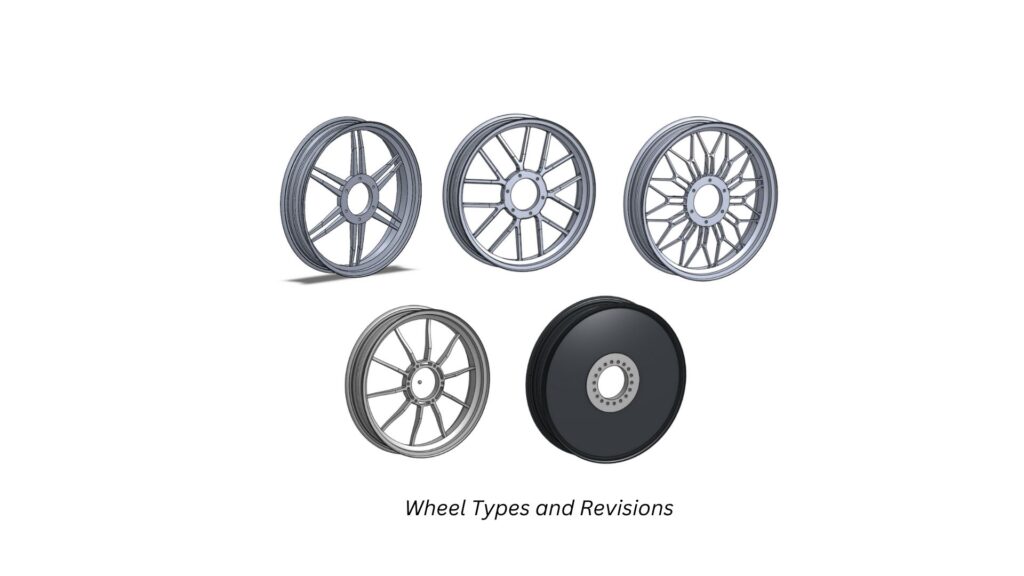
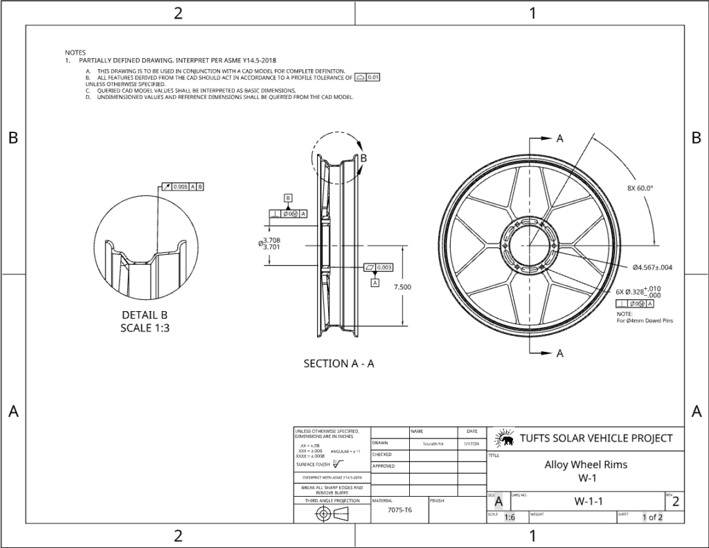
Metal rims ended up costing about $1000 per rim. Although much more affordable than off-the-shelf rims, they were still expensive. I found that carbon fiber was actually a more affordable option as there is no material wasted in machining. So I decided it would be worth spending time trying to build these. There were, however, a host of problems with my idea.

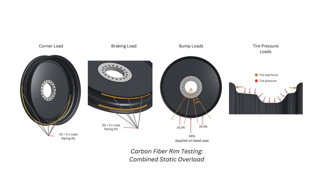
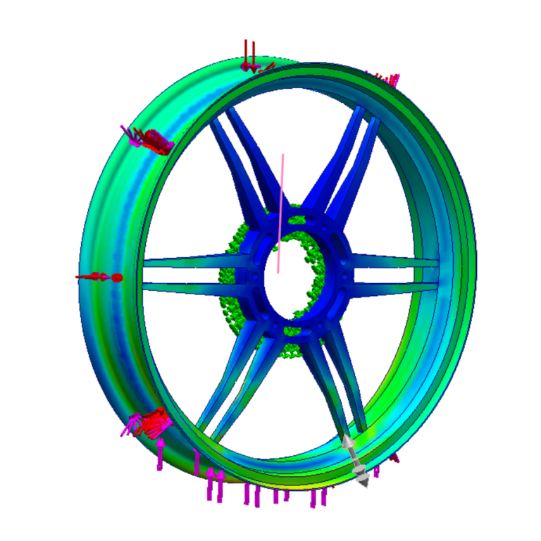
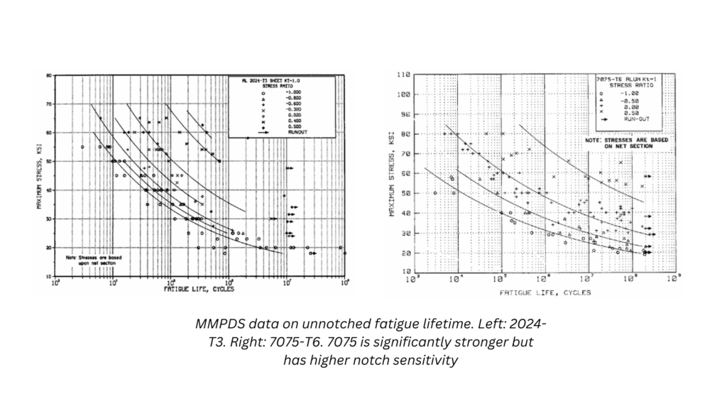
First, fatigue lifetime of carbon fiber cannot be determined without extensive testing and equipment that we did not have access to. Thus, I compromised by doing a static simulation with the same loads I applied to the front suspension, but doubled to be conservative. The loads were: 4G bump, 2G corner, 2G braking. I modeled a quick surface-model similar to the metal rims I designed earlier and set it up in Altair Hyperworks as a composite simulation.

Knowing where to apply the loads was quite challenging. It took a lot of though to determine how the tire transfers the load to the rim. I eventually refined a method by looking at papers that studied the tire-rim interaction. The key forces come from the pressure of the tires, and the regular loads being transferred from the tire patch to the bead seats.

It took a while to figure out the details of Hyperworks – there were a lot of loads being applied at the same time. Carbon fiber is orthotropic, so the material properties had to be experimentally derived. See my chassis write-up to see how we did this! 

I refined the number of plies and the fiber orientation. With all thicknesses determined, I could move on to figuring out how to produce the rims. 

Failures & Lessons

My first mold was meant to be made with MDF for its low price. I intended this mold to be a proof of concept to show that it was possible to make carbon rims relatively easily. I made it out of four parts in a the CNC router in Tufts’ maker space.

When I put it all together though, I found the parts did not align with each other well. MDF was not dimensionally stable, and I had not machined aligning features to line everything up.

I restarted but this time, decided to make a male mold so it would be easier to refine the shape of the mold to get it perfectly circular. This time, I built in aligning features so things would hopefully line up better.

Unfortunately, the dimensional instability of MDF meant that by the time I had the second half machined, the parts didn’t snap well with each other. There were clearly high spots and the finish I found was not as easy to sand as I had hoped. I decided to quit as bringing this mold to work would have taken too much time, and having a working result was not a guarantee.

The benefit of metal rims was that the manufacturing process is well known enough that it was not a risk. Ultimately, the failure of the project taught me that time and risk is worth money.

References

  1. The Society of Automotive Engineers of Japan, Inc. (1985). Japanese Automobile Standard JASO T 203-85.

  2. al-Khazraji, A. N. I. (2010). Effect of heat treatment on fatigue life of Aluminum alloys 2024 and 7075. Engineering and Technology Journal28(22), 6469–6481. https://doi.org/10.30684/etj.28.22.2
  3. Dhafir Sadik Al-Fattal, Samir Ali Amin Al-Rabii, Ibrahim Mousa AL-Sudani, Effect of Anodizing Process on the
    Mechanical Properties and Fatigue life of Aluminum Alloy 2024-T3, 2016. Journal of Applied Sciences Research. 12(11); Pages: 9-
    17