One of my most fun projects has been designing TSVP’s first car’s steering system. Initially, I thought making one from scratch too challenging, and I wasn’t confident in my ability to make something durable enough for my team to trust it as an integral part of the car. However, as the design of the chassis converged to what it became, I found that there was no off-the-shelf steering rack that suited the needs of the car well.
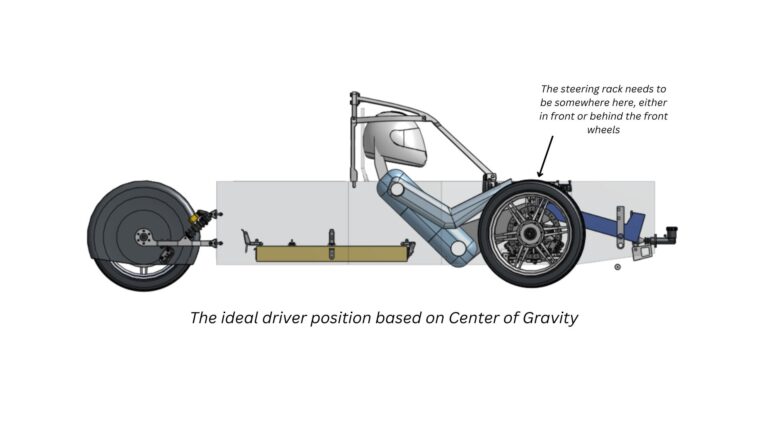
Being a three-wheeled tadpole, the ideal weight distribution of the car is biased forward at 66%-33% (front-rear). However, given the stability of the car is assessed based on the maximum angle it can tip on a front wheel and the back wheel, having the weight distribution be further forward than ideal helps us get a vehicle less likely to tip over. This has the effect of allowing us to make the car narrower for better aerodynamic efficiency.
After messing around with the position of the heaviest parts of the car, I found the optimal position of the driver to be quite far forward and almost above the front wheels. This would mean there would be little room for the steering assembly.
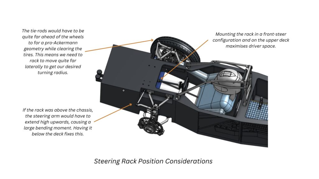
I tried a few different layouts but converged to using a front-steer configuration, placing a steering rack under the top deck of the carbon chassis. This would maximise space around the driver and ensure they can get in and out relatively easily.
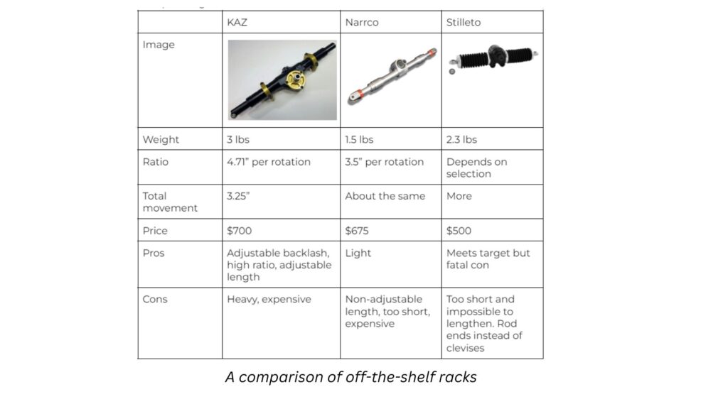
With the position set based on packaging, I could then derive the following specifications: Maximum rack travel > 90mm, Steering ratio < 3.25 turns/rev. None of the off-the-shelf racks worked for this as they were more targeted towards FSAE or similar racing configurations. They were also quite expensive, which is a high-weight consideration being a new team.
How I got to the current design
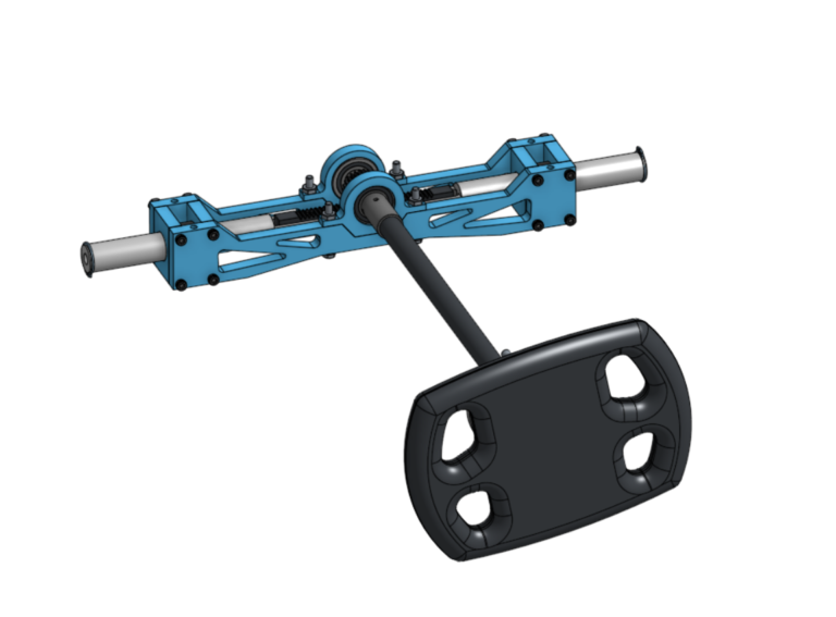
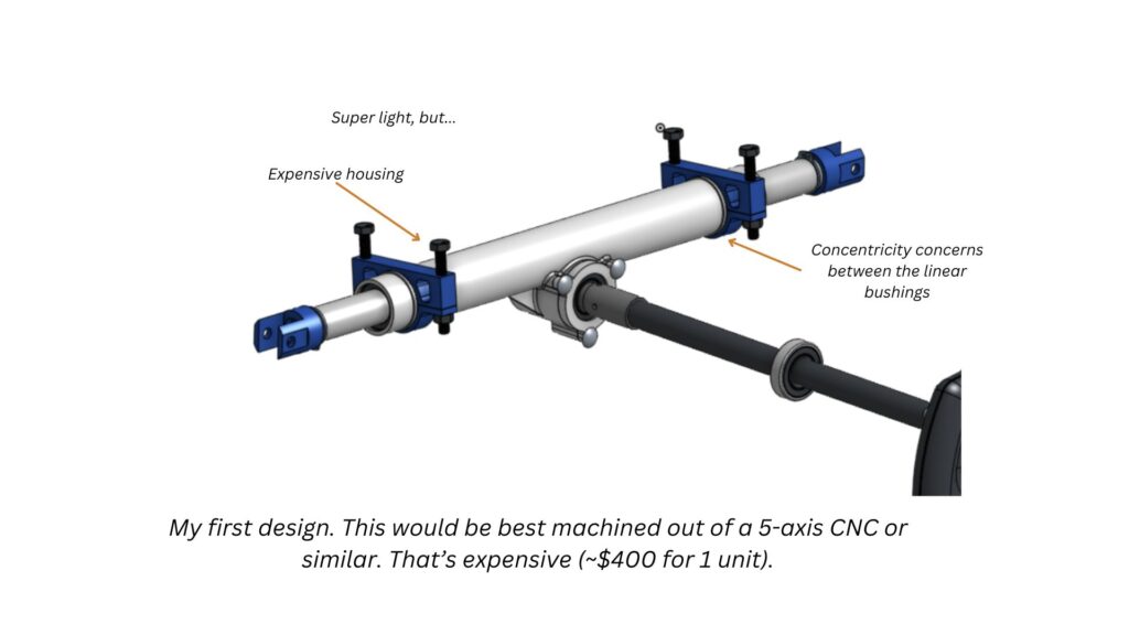
So I decided the best course of action was to learn how to make one, fully understand what goes into the design, and only buy a pre-made rack if there was an obvious drawback on manufacturing barrier. My first design was based off images of pre-existing racks, and had some serious drawbacks in cost and manufacturing. That said, being able to control each component allowed me to control the gear ratios, maximum travel, and rack length to perfectly suit our car.
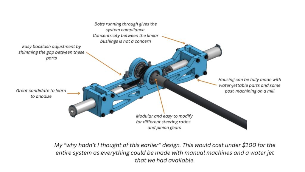
Our manufacturing capabilities were limited, so the housing would’ve needed outsourcing. After giving it a thorough think through, I came up with a non-standard second version that I like much more.
Next Steps
The obvious next step would be to build the thing. I’ve already spend lots of time on the lathe getting my skills up to scratch for a good surface finish I could still spend more time practicing, but this would be an excellent project to help with my shop skills. I also thought of the following improvements:
1) Instead of shims, add springs and a locking mechanism for easier, tool saving backlash adjustment mechanism
2) Figure out a pin or locking system such that the rack is held in the circular bond with more than just adhesive
And we need to build it. Fortunately, this should be pretty easy to do.