Solar car races are endurance competitions that span long distances (1500-2000 miles per race). We are allowed to have a very small battery that would give us a small amount of range, but not enough to cover the entire distance.
The performance of the car in the race is thus tied to its energy balance. A good performing car will collect lots of energy from the sun while being electrically and aerodynamically efficient such that it sips on the battery pack. Aerodynamics is the most important part of efficiency of our car as aerodynamic drag increases exponentially with speed. However, a shape optimized for aerodynamic efficiency is often at odds with good solar collection.
This article will cover two sections. First, the aerodynamic design of the car in which I discuss the overarching decisions that were made. Next, the model in which I created a vehicle model to balance aerodynamics and solar collection.
Types of Designs Considered
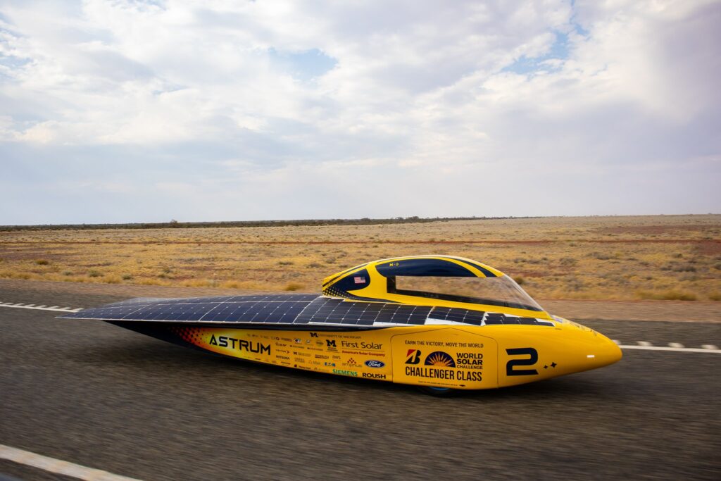
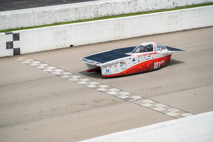
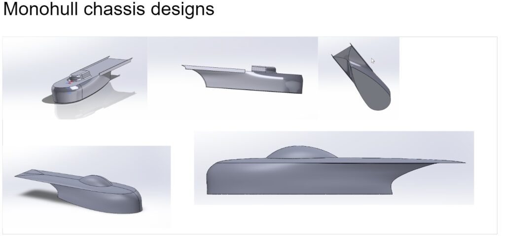
Monohull "Bullet"
Pros: High Aerodynamic Efficiency, Low cost, Low weight.
Cons: Narrow footprint means low stability, high chance of rollovers, poor crosswind performance
Symmetrical Catamaran
Pros: High stability during turns, Converts crosswinds to forward thrust, simple layout, less solar shading from canopy.
Cons: Poor aerodynamic efficiency, 4 wheels required leads to more rolling resistance, Heavier, Higher suspension loads due to fairings.
Cons: Asymmetrical steering required, Weight distribution heavily skewed towards driver side, More drag than bullet.
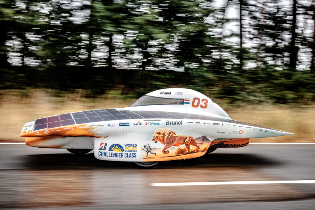
Monohull "Pod"
Pros: 3-wheeler configuration, Optimized solar array direction, No canopy shading.
Cons: Moderate-high drag, Narrow footprint and high bodywork leads to instability, Heavier than bullet.
Decisions & Initial designs
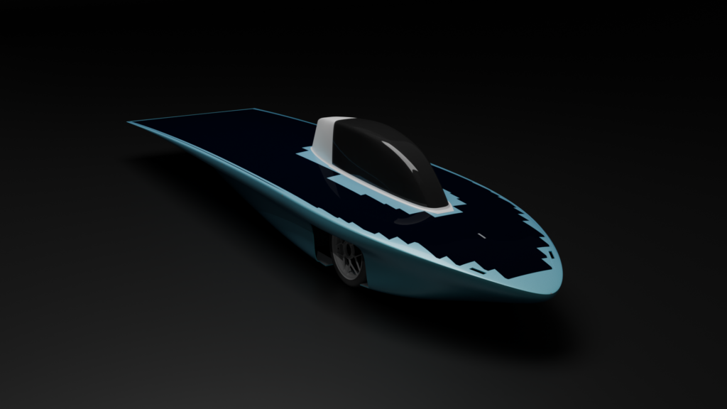
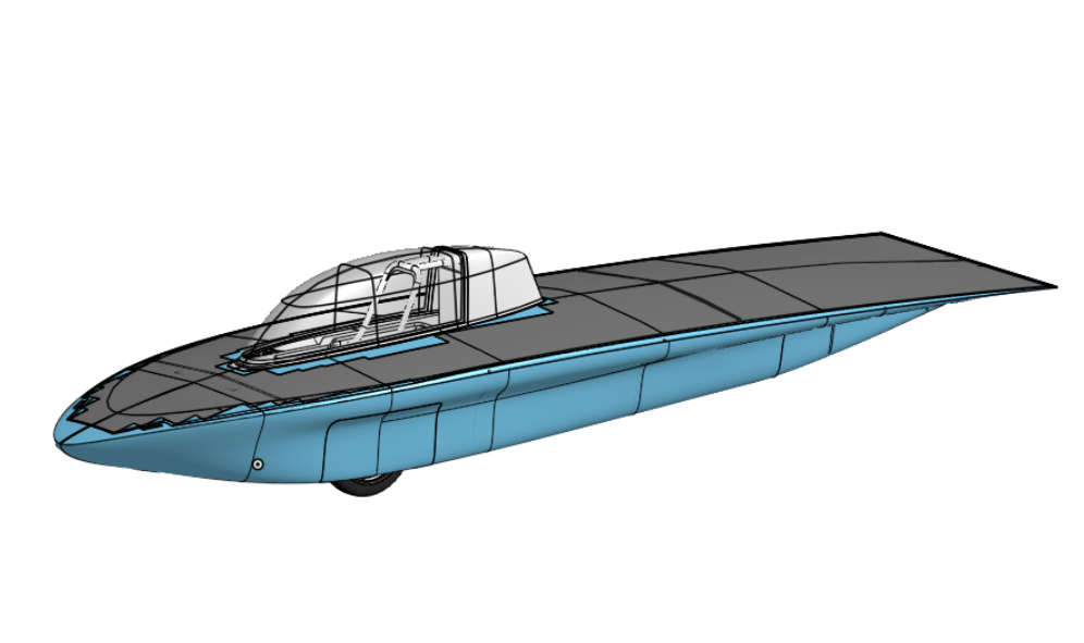
Since we were building our first car, the choice to go with a bullet style monohull was easy since it would be relatively affordable, is very simple to make, and easy to make visible progress in as everything was to be mounted onto a smaller chassis.
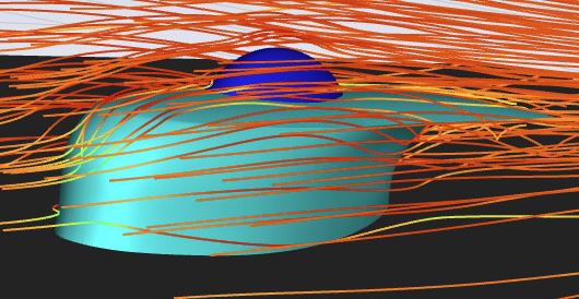
As I had to start from scratch, I had no data on which I could compare my designs with other teams. So, I jumped through several hoops to get Ansys Fluent, watched tutorials online, then set up straight-line simulations in which I could collect data on models. My first models were terrible as I got to grips not only with surface modeling, but coming up with a design completely from scratch not knowing where to put things, how big the wheels were, how wide it needed to be, etc.
My very first design that I ran through Ansys Fluent. My undergrad program didn’t teach in Fluent so I had to self-learn with online videos.
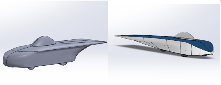
Progression of the body and my surfacing skills throughout two years.
Design for Manufacturing and Tooling Design
The entire exterior of the car was to be made from carbon fiber for weight savings. As the number of seams needed to be minimal for optimal aerodynamic efficiency, We needed to make large molds in which we could layup our carbon fiber and cure it into shape.
For the part to be effectively release from the mold, I needed to have appropriate draft angles. As the car needs continuous edges with at least G1 curvature, I could not avoid regions of near zero draft angles. However, I did try to minimize it without affecting aerodynamics.
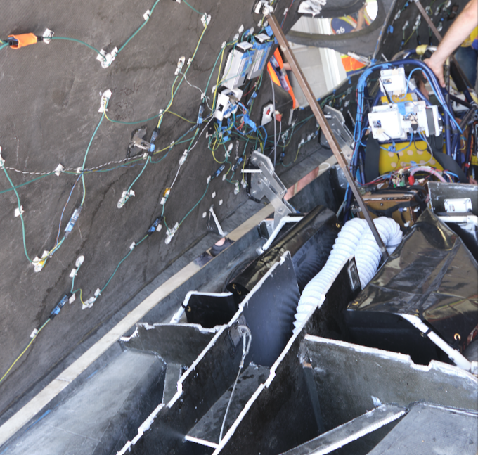
One specific area I paid a lot of attention to was designing for the interfaces on the car. For example, the top shell with solar arrays is meant to separate from the bottom shell so it can be pointed towards the sun. At the competition I attended, I saw many cars splitting the car at the split line between the positive and negative draft angles. This lead to trouble with alignment when closing the shell.
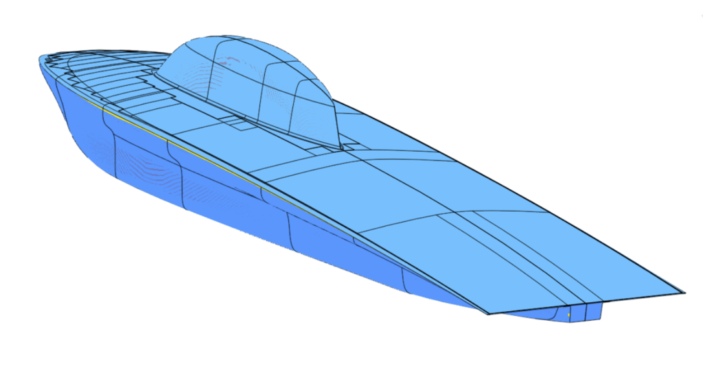
Draft Analysis showing steep regions in yellow and the two main sections. I added subtle draft angles to the number plate region at the rear and tailored the nose for a sharper split line.
Example of a solar car with a poor top-bottom shell interface. The team had trouble lining up the sharp edges of the parts as there were no aligning features.
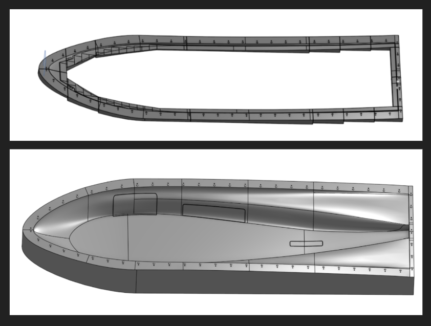
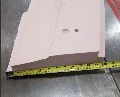
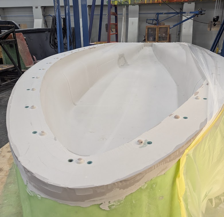
To make the recessed flange while ensuring we can get the part out after curing, I created another mold part – the “flange mold”. You can also see here the recesses for the wheel covers and battery box, and trim lines for holes where the wheels would be.
The flange mold has similar locating features. We intend to drive screws through the top into designated threaded holes in the lower shell mold.
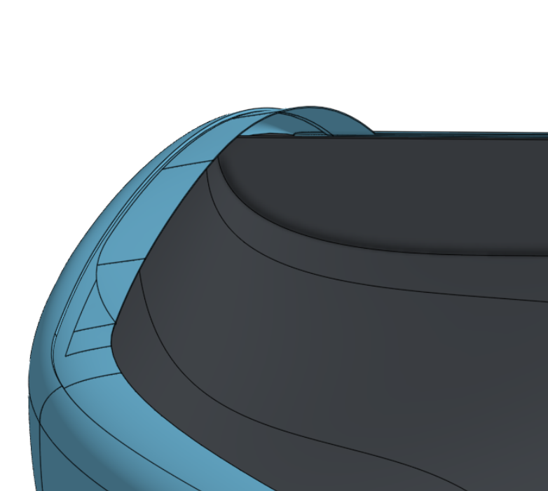
My design is not split at the parting line. Instead, I added a flange with a recess so the top shell will snap into the right position.
I sent the mold designs to Symmetrix Composites for manufacturing. They’ve made molds for SpaceX, Beta Technologies, and a host of other companies. They had great advice for creating locating the top and bottom sections through half-spheres that I implemented in CAD.
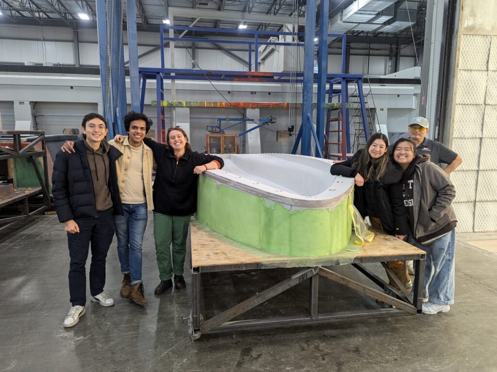
Transporting the molds between Massachusetts and Rhode Island was a massive logistical challenge, but seeing everything come to life made it worth it.