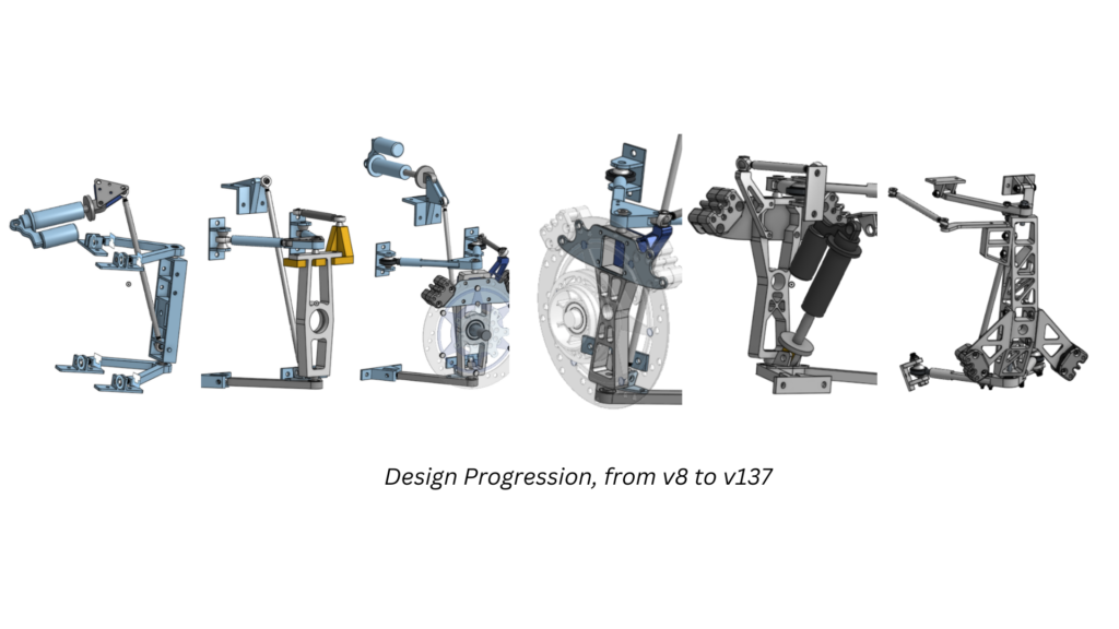
Suspension gets very complicated quickly, and I wanted the suspension to be simple and “just work” so it is not a reliability concern when racing. Even then, however, this took a lot of iteration as I deepened my understanding of what needs be considered in design, and as the rest of the vehicle developed.
Skills developed:
CAD of complex assemblies.
Engineering drawings with specified fits and tolerances.
Design for CNC manufacturing.
Project and time management.
Finite Element Analysis (FEA) and optimization
MATLAB, mechanics calculations
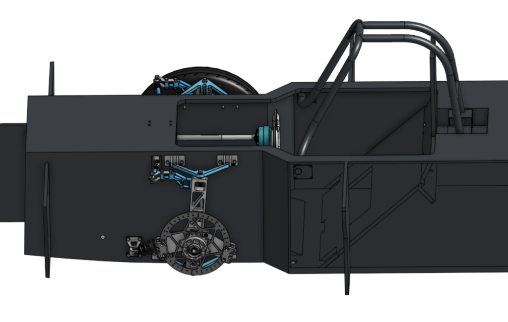
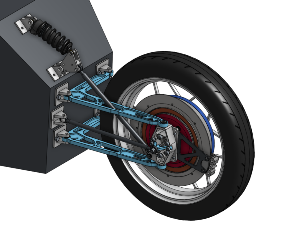
Front Suspension Design
I decided on a double-wishbone system for the front. This is something I understand the best, and it allows for lots of control over the entire suspension assembly. It also is very light, and packages nicely with the chassis without any additional mounting extensions. My main requirements were:
Low plane-normal forces transmitted to the chassis. Carbon fiber is strongest with forces in the direction of the fibers, or along the plane of the chassis.
Tight packaging to allow for a narrow vehicle.
Easily adjustable and removeable for easy maintenance.
Lightweight and with a low center of gravity.
Reliable and Durable – no rod ends in bending, appropriate safety factor for 4G bumps and 1G corner and braking loads.
Manufacturable with a 3-axis CNC Mill and/or metal 3D printing.
Sufficient travel with no collisions within the assembly for the complete range of motion.
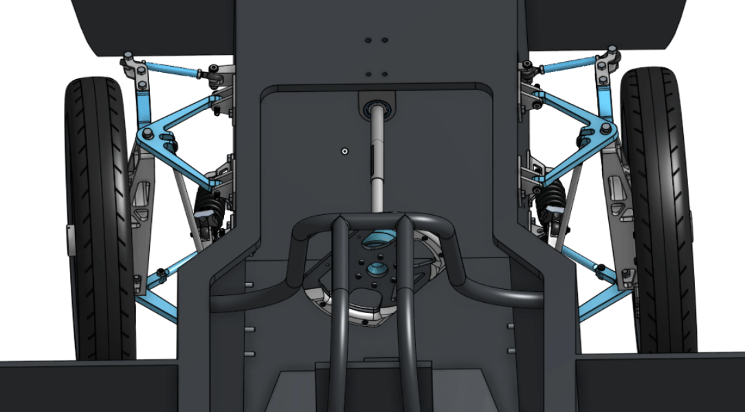
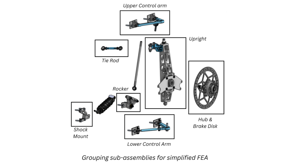
Testing motion of the steering and the shock to ensure the car meets a minimum turning radius and there is sufficient travel and shock usage. All parts shown are drawn by me in Onshape.
Determining Specifications
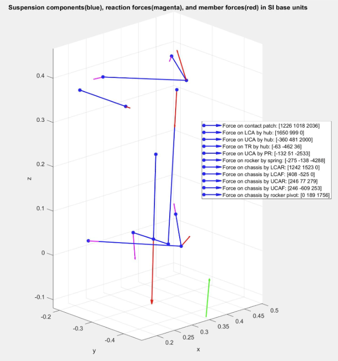
To fully define the problem, I needed to determine what the designed loads were. Based on data from other solar car teams and the regulations, I aimed for a 4G bump load for when the shock hits its bump stops, and a 1G corner and brake load. I would add all of these loads at the contact patch of the tire and ground concurrently to model a worst-case scenario, and aim for a minimum FOS of 1.5.
I found quickly, however, that modeling an assembly with as many degrees of freedom as this was computationally taxing. I solved this by creating a MATLAB script with a teammate to find the loads at every node of a beam-model. Pictured is a representation of the loads that were found, which I could then use as boundary conditions to perform FEA for individual components.
Iteration
I refined the suspension by iterating through static load simulations. I found that cutting triangles in two operations would yield diagonal braces that improved the strength-weight ratio of the assembly. I also learned a lot about materials and determined that 7075-T6 aluminium would be the far superior choice in this use case without adding too much cost.
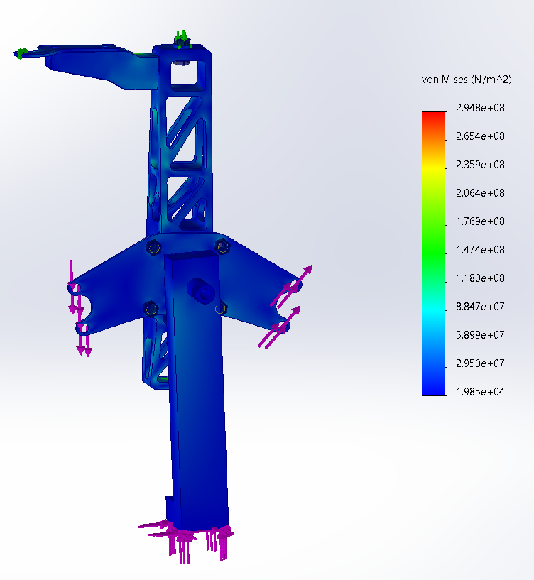
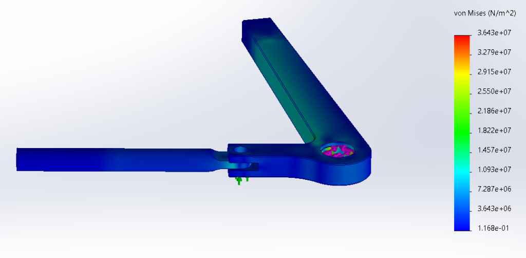
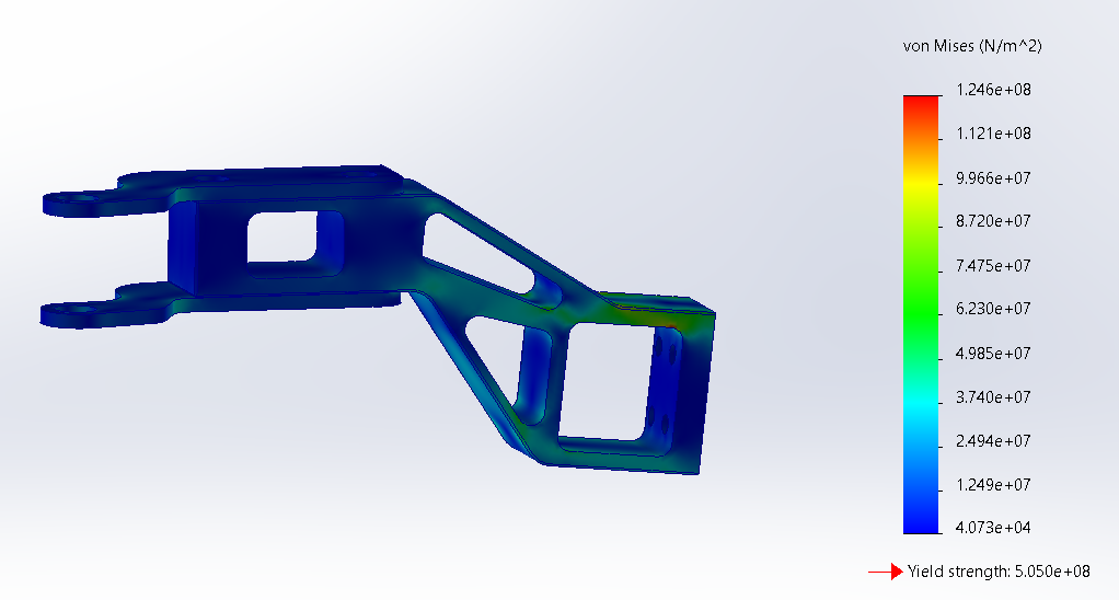
Sample Simulation Plots
Upright Stress plot
Lower Control Arm Stress plot
Steering Arm Stress plot
Manufacturing
To reduce costs, we are outsourcing the machining of some parts and making some of them in-house. The parts being outsourced usually include parts that are in quantities of more than one, parts that require multiple setups and have complex geometries, large parts, and parts that require custom fixtures.
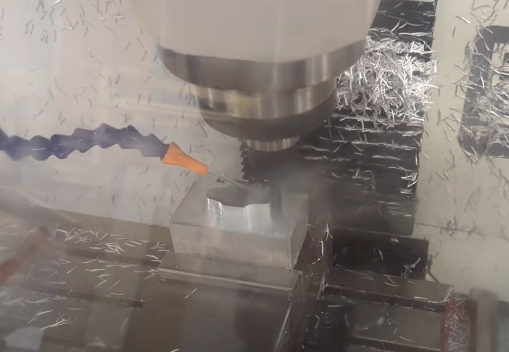
One-off and small parts used to be something we would outsource, but our makerspace recently acquired a Tormach 440C. There aren’t many people who have used it, so I’ve been learning to use it in my own time and have had enough success to develop tool libraries and SOP’s.
CNC Milling a test part on the Tormach. I identified areas for improving CAM and the setup to fix issues with chatter and optimize the machining time.
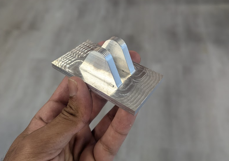
The completed test part – a bracket for the lower control arm. There were areas with poor surface finish that I fixed with different toolpaths.
Challenges
The biggest challenge was around ensuring the assembly achieved the appropriate travel and turning radius required without parts colliding. As the wheelbase of the car is narrow, the wishbones have to be quite short. This means that to get reasonable travel, the control arms will vary in angle quite a lot. Additionally, the car has a very long wheelbase to meet regulations. As a result, the wheels have to turn quite a lot to achieve the minimum turning radius stipulated in the regulations.
There were also plenty of other challenges such as:
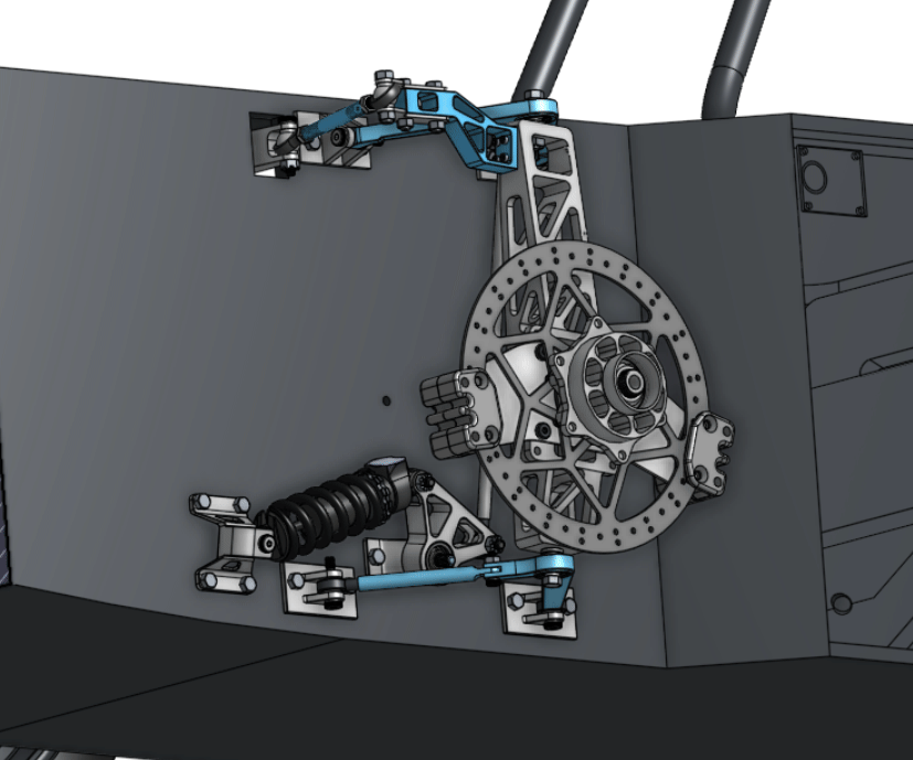
Preventing stress concentrations on the connection between the upright and the upper wishbone that carries the resistive load of the pull-rod.
Ensuring the steering arm was stiff enough but still modular to allow for adjustability if we found through real-world testing the Ackermann geometry I designed with was not optimal.
Ensuring the brake caliper mounts did not flex too much under heavy breaking loads and that the fasteners were loaded correctly to transmit the forces into the upright.
Making the uprights easily manufacturable with the Haas VF2 CNC Mill we had in the school’s machine shop. I tried to ensure that the whole part could be made in no more than two setups.
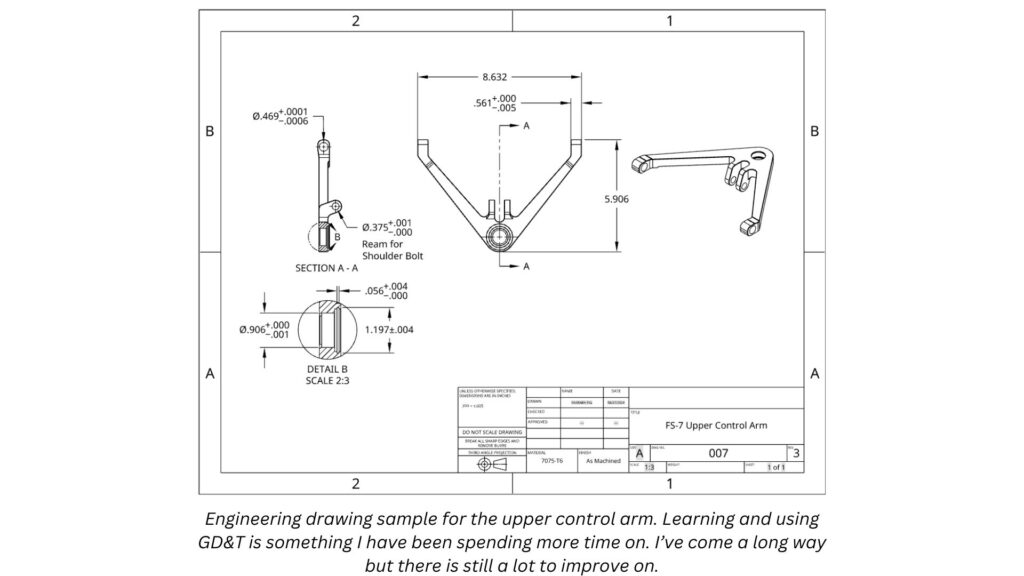
Alleviating risk by making engineering drawings. Nobody taught me how to make these in class and specify tolerances, so I had to learn from the internet and by making several mistakes with machine shops.
Overall, the front suspension assembly reflects the progress I’ve made over the past two years since taking on this project. I’ve learned some tough lessons. Two mindset focused lessons include:
Account for failure. I spent lots of time on making parts, discovering I did not have the skill to make them consistently well, then getting disappointed by the progress. I’ve since adjusted my design mindset to account for failure as part of the design process. Now, I try to make my way to the first failure as fast as possible and accept it as part of the prototyping process.
Time is finite and worth money. I started many projects concurrently and often ended a semester with many half-done projects. Since then, I’ve made improvements to the way I delegate tasks within the team and decide what to make in-house and what to employ others to make.
In terms of technical skills, I have lots to learn on:
G,D, & T
Selecting appropriate fits with tolerance charts
Working with others with drawings and BOM’s
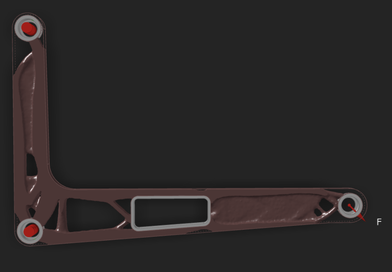
Rear Suspension Gallery
Topology Optimization results for weight savings on the rear control arms
Nearly finalized rear suspension system designed for CNC milling.